It's been a bit since I last posted, but for good reason. In the past two weeks I have frantically made the last adjustments and accommodations before test firing. I also got to ship out and visit Princeton, which was quite fun.
NOTE: I'm posting this from a computer other than my own so I can't upload the pictures until I get home tonight. There are pictures I promise!
The main preparations I've made are to finalize the data acquisition system and to ensure the fuel grains and ignition are ready to test. The data acquisition system initially seemed difficult to tackle, but the school allowed me to borrow a Labquest 2 unit, which greatly simplified things. The only problem is that my pressure transducer that taps into the rocket's bulkhead puts out an analog voltage signal, and the Labquest is only capable of receiving digital signal via either USB or ethernet ports. The simplest solution appeared to be to order a voltage probe for the Labquest, which the physics department promptly got done (Thanks, Mr. Clark!). Using that, I am able to plot voltage vs time on the Labquest, and in turn calculate the pressure in the rocket at any given point. Using a modified version of P=F/A (pressure is the quotient of force and area), the force produced by the rocket at different points in time will be solved (and an integral could be used to find the total kinetic energy produced).
One of the problems in using a analog pressure transducer is that it requires a steady power input to operate. The output of the transducer is between 1 and 4 volts, and the power input of the transducer should reach that. It should also be constant, as to reduce power fluctuations that would cause the analog voltage readings to not properly reflect the pressure in the bulkhead. The solution to this is to use a voltage regulator with the power supply. The power comes from a standard 9V battery, but the voltage regulator provides a power supply that is consistently a perfect 5V for as long as the output of the battery is greater than 5V.
The fuel grains are the other mater. My grains don't cure. They never cure. This is frustrating. On my last batch of grains (HTPB/Al and HTPB/Al/PVC) the composition of MDI (the agent that causes liquid HTPB to set as a solid rubber) was already 20% by weight. This is HUGE! A typical batch (albeit on a larger scale so molecular interactions over time are different, plus a typical batch is mechanically stirred for hours whereas mine are hand mixed for several minutes) is 15% by weight. Mine weren't solid even at 20. So I ripped out the semisolid, supersticky HTPB (my hands have been covereded in it for almost two weeks). This task was very difficult.
Upon making the new grains, I upped the MDI percentage to 25. This is massive. Detracts from the actual fuel weight in the grain, meaning the fuel grain stores less energy and will not burn as effectively. But this power sacrifice is necessary, because perfectly solid fuel is incredibly important. If the fuel flows in any manner, it risks plugging the nozzle and causing a dangerous pressure buildup in the case that could blow the assembly sky high.
One thing I've noticed is that I have developed an allergy to the MDI, as many people do (yes, the Swedes did a study on it, I'm not alone in this). So in addition to being a nasty irritant to skin, it also causes me to have an allergic reaction in areas of contact. It's been two weeks with a this irritatio on my forearms, back of my hands, and a little on my forehead as I stupidly wiped the sweat off my brow with such contaminated forearm. And even when I thought I started to heal, I accidentally dumped a syringe-load of MDI right back on the affected forearm. I'm stupid. But rocket science is messy.
From what I see and experience at the lab, rocket science isn't glamorous. It's hard, messy, filled with slagging metal and aluminum oxide, reactions that misbehave, and plenty else to gripe about. But that's what makes it enjoyable. The challenge is what motivates.
Next week is testing week! I'm far behind schedule with testing because of many many many unforeseen obstacles. It's long overdue, and it's going to be great.
Thursday, May 1, 2014
Monday, April 14, 2014
Intermolecular Forces Strike Again
When it came to pouring the asphalt fuel grains, I did not anticipate how long it would take. Starting with approximately ten pounds in two large chunks, I pulled/sliced the bitumen (asphalt without the gravel-just the tar) in small pieces. This was more difficult than I thought... the long, high mass hydrocarbons in the asphalt would not let go of each other. With a teflon pan I started to melt the chunks of asphalt over a hot plate, trying to evenly heat the black pitch into a uniform liquid. This proved daunting, as the asphalt much preferred the solid state, and refused to melt. After probably half an hour of coaxing, I filled half of one phenolic tube with liquid asphalt, leaving another tube and a half to go. It became apparent that it would just be easier to pick up the asphalt on an aluminum stick and melt it with a blowtorch than to use a pan. The whole time, between the spatters of hot pitch (the same material they used to tar and feather people in the days of old; I can only imagine the horrific burns they suffered across their bodies in addition to the public shaming), I was continuously taunted by the pesky properties of this hydrocarbon amalgamation. Next time I'll just drive to the La Brea tar pits and dip the grains in-it'd almost be faster that way.
Another major objective was to drill/tap a hole in the bulkhead where a pressure transducer could fit. This was necessary because without the pressure transducer, I would not be able to quantify force/pressure vs time in each rocket testing. The end result was not pretty, but works. However, I made a terrible mistake and partially destroyed the threads that allow the bulkhead to screw into the combustion chamber. The damage was mostly repairable and I avoided having to start all over in making/modifying a new bulkhead.
Later in the week, I began to experiment with the HTPB fuel grains. HTPB (hydroxyl-terminated polybutadiene) is a liquid rubber base, and in the presence of MDI (Methylene Diphenyl Diisocyanate), cures rapidly into a solid rubber. I used other additives in making the fuel grains. I planned to make two HTPB basic grains, and one with powdered magnesium as a fuel additive. Each fuel grain followed a basic mixture as follows:
40g HTPB
8g MDI
2g CuO (cupric oxide), a stabilizer and fuel supplement
~20mg Triphenyl Bismuth, a contaminant that allows for quicker ignition
The Mg+HTPB grain also included 5g Mg. This was all relatively easy, with the exception of extracting MDI from its storage container. The barrel is very tightly sealed, as MDI reacts very quickly with water, tearing apart the isocyanate and rendering the MDI useless. Additionally, MDI should be kept in a controlled climate, meaning the barrel is housed in a foam igloo. MDI also has very low viscosity, making extraction via vacuum somewhat difficult, as the vacuum seal was not perfect and allowed MDI to drip very quickly back into the barrel and out of our reach. Oh, and it's harmful to skin and lungs, pretty harshly so. Anyways, after mixing all the components, I cast the rubber into the phenolic tubes, each capped with aluminum tape to prevent leakage. They look like huge shotgun shells.
After this, Robert and I constructed the control box, a task that we did incorrectly. I have to go move some wires and resolder after I post this. Simple fix.
Fast forward to today, after a long weekend. The nitrous valve is mounted, the tubing is in, the bottle is oxygen-cleaned to ensure safety. All this would be great, but there was one large complication.
The HTPB grains didn't cure.... Critical Mission Failure.
The two pure rubber mixes were still incredibly liquid, which by a strange twist of fate, was much better than the magnesium-HTPB grain. How do I describe it? The Mg grain was sticky like glue, stretchy like putty, and is like bread dough from hell. And toxic. But oh it's a very nice color... I think I ought to sell it as a premium automobile paint color... Anyways... since I didn't want to waste the phenolic tubing by throwing away the whole grain, I had to remove the fuel. What a task that was. After half an hour, it was all out. The intermolecular forces really taunted me there. I can imagine all those electrons, each participating in a subatomic tug-of-war against me, completely determined to make me waste my time.
Tomorrow I will revisit HTPB. I am increasing the proportion of MDI to be 20% by weight, hopefully enough to fully cure each grain. I want to be a chemical engineer so I better get used to finicky reagents.
I am on schedule to fire by Thursday, or Monday at the latest. Thanks for viewing.
 |
| Melting Asphalt |
Another major objective was to drill/tap a hole in the bulkhead where a pressure transducer could fit. This was necessary because without the pressure transducer, I would not be able to quantify force/pressure vs time in each rocket testing. The end result was not pretty, but works. However, I made a terrible mistake and partially destroyed the threads that allow the bulkhead to screw into the combustion chamber. The damage was mostly repairable and I avoided having to start all over in making/modifying a new bulkhead.
| Bulkhead with Transducer Fitting |
Later in the week, I began to experiment with the HTPB fuel grains. HTPB (hydroxyl-terminated polybutadiene) is a liquid rubber base, and in the presence of MDI (Methylene Diphenyl Diisocyanate), cures rapidly into a solid rubber. I used other additives in making the fuel grains. I planned to make two HTPB basic grains, and one with powdered magnesium as a fuel additive. Each fuel grain followed a basic mixture as follows:
40g HTPB
8g MDI
2g CuO (cupric oxide), a stabilizer and fuel supplement
~20mg Triphenyl Bismuth, a contaminant that allows for quicker ignition
The Mg+HTPB grain also included 5g Mg. This was all relatively easy, with the exception of extracting MDI from its storage container. The barrel is very tightly sealed, as MDI reacts very quickly with water, tearing apart the isocyanate and rendering the MDI useless. Additionally, MDI should be kept in a controlled climate, meaning the barrel is housed in a foam igloo. MDI also has very low viscosity, making extraction via vacuum somewhat difficult, as the vacuum seal was not perfect and allowed MDI to drip very quickly back into the barrel and out of our reach. Oh, and it's harmful to skin and lungs, pretty harshly so. Anyways, after mixing all the components, I cast the rubber into the phenolic tubes, each capped with aluminum tape to prevent leakage. They look like huge shotgun shells.
 |
| The Fuel Grains Curing (well, not really curing....) |
After this, Robert and I constructed the control box, a task that we did incorrectly. I have to go move some wires and resolder after I post this. Simple fix.
Fast forward to today, after a long weekend. The nitrous valve is mounted, the tubing is in, the bottle is oxygen-cleaned to ensure safety. All this would be great, but there was one large complication.
The HTPB grains didn't cure.... Critical Mission Failure.
 |
| Left: Failed Fuel after Extraction. Right: Empty Phenolic |
Tomorrow I will revisit HTPB. I am increasing the proportion of MDI to be 20% by weight, hopefully enough to fully cure each grain. I want to be a chemical engineer so I better get used to finicky reagents.
I am on schedule to fire by Thursday, or Monday at the latest. Thanks for viewing.
Thursday, April 3, 2014
Graphite Dust, White Shirt
All in all, it was a good day. But not for my white shirt. My electrode-grade graphite rod came in, and that was all I needed to start fabricating the nozzle. What I thought was going to be incredibly laborious ended up actually being very simple. Rather than follow my plan as explained to my BASIS advisors (sorry guys), I decided to ditch using the lathe altogether. The lathe at Mishaal can only grab items larger than 2in diameter; the graphite rod is 3/4in. Not wanting to putter around trying to make a collar to hold the graphite rod in the lathe and wait and wait and wait until it finished, I decided to use the drill press instead. My on-site advisor Mr. Loehr and his son Robert keenly brought out an array of drill bits that could be improvised for reaming the graphite piece.
Using a hacksaw, I lopped off roughly 3/4in of the graphite rod, held in a vice. I wasn't careful, and gravity pulled the piece off before I could finish it with a clean cut. This resulted in a chip in the graphite and a bit left to file down. After this, I drilled a 1/8in pilot hole through the small graphite cylinder, shown below. I thought it looked like a cinder cone volcano-the red laser beam looking like flowing lava. As much as I thought it was an industrial piece of art, I had to blow the dust off and stare at the pilot hole, just a tiny bit off-center (the drill press sucks, it wobbles, and the belts come loose. Every guy in the shop is waiting anxiously for a new one).
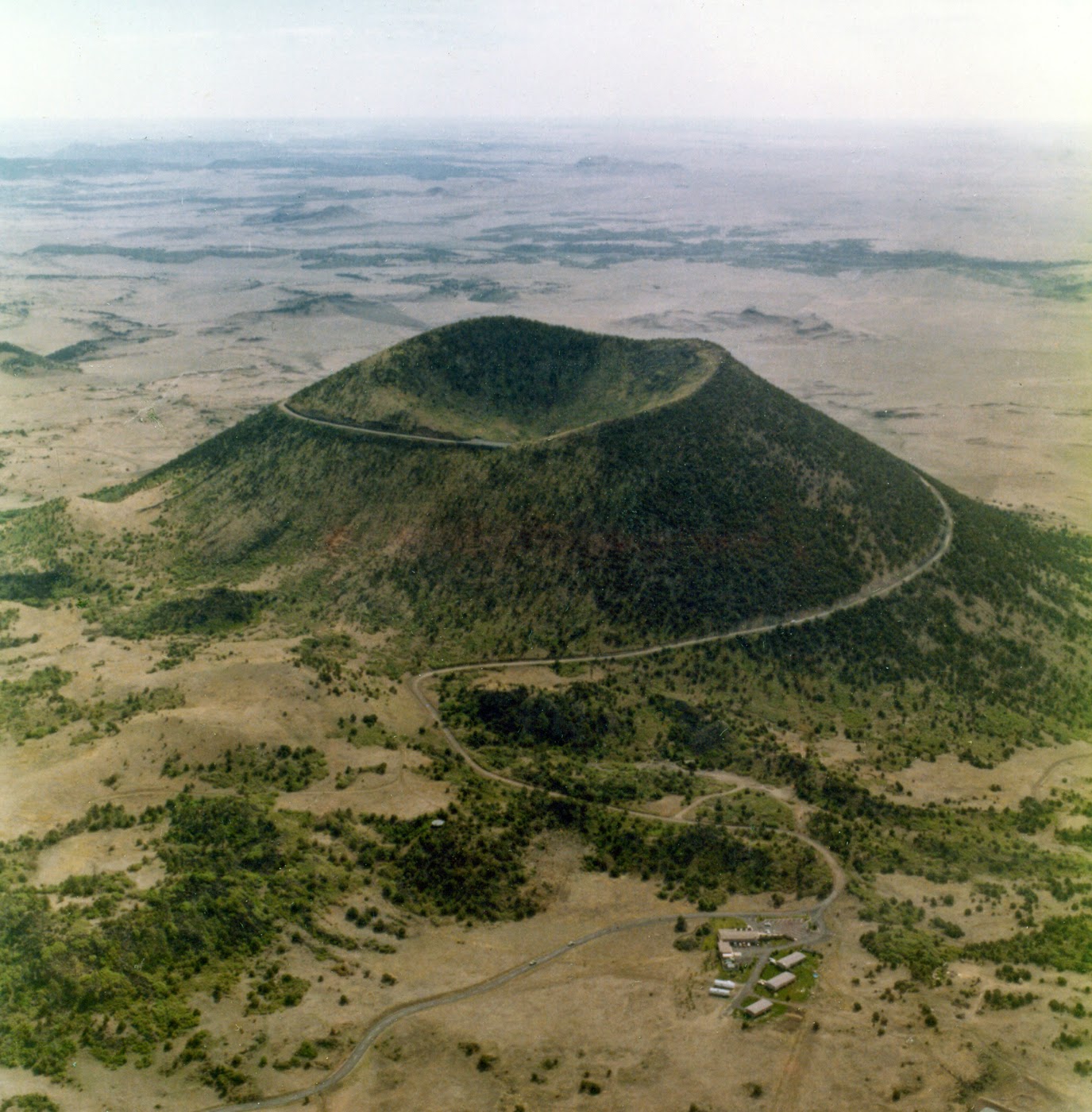
 Left: Cinder Cone volcano in Utah. (wiki images) Right: Graphite Nozzle after drilling pilot hole. Click to enlarge.
With a 15/64in drill bit, I bored through the nozzle. My throat has to be 1/4in, so I accounted for the wobble and sized one bit down, yielding a nice 1/4in diameter throat through the graphite nozzle. Only it wasn't centered. I repeated the process, more careful with the hacksaw and centering. The second attempt worked beautifully. To finish the nozzle, I had to taper both ends. Here is the diagram:
The convergent end of the nozzle (noted as 'CONV' on the diagram, left side) is the piece that is on the interior of the rocket. It is where the gasses produced during reaction seek to escape, and it is important that the interior wall of the nozzle be smooth here. Using a boring drill bit (gray, far left on image), we achieved roughly a 30° half-angle taper. Success. For the other side, the divergent end (DIVR), where the gas escapes and creates thrust as it expands, we used a step drill, a drill bit that has wider and wider sections as it goes in (bronze, rightmost on image). This achieved roughly a 15° half-angle, stepped of course. A small section of 1/4in throat lies in between the convergent and divergent holes. This is a successful, well made nozzle, if I may say so.
The nozzle is a tad small for mt rocket chamber, but some O-rings will wedge it in just fine.
 After this, Robert and I tried to mount the nitrous valve to the aluminum sheet holding up the rocket, but our quick method of using zip ties just didn't hold. We moved on to putting a small section of 1/8in nylon tubing into the rocket's bulkhead, and it will connect to the nitrous valve in the future.
The nylon tubing is wonderful because it has a burst pressure of approximately 1500psi. That means that if there was a backfire with the rocket, the nylon tubing will rupture, rather than letting the reaction travel into the nitrous valve and blow up my $42-with-free-shipping gadget.
After this, I thought I would take off. However, I decided to watch as some experiments were going on. Friction Stir Welding. Never heard of it? Neither had I until today. But it's about the coolest damn thing ever (if you're into this stuff at least). The premise: weld two pieces of metal together without melting either. "What? How? That doesn't make sense," I said, as you might be saying yourself as you read this. I can't say I fully understand the specifics, but I'll try to explain best I can:
1. A high pressure, high rotation speed (1000-2000 rpm) specially made drill bit presses into the crease between two separate aluminum coupons.
2. It bores a hole, and starts slowly moving along the border between the two sheets of aluminum.
3. The heat and pressure and movement from the friction of the drill bit increase the plasticity of the metal, and literally mix the still-solid aluminum from both pieces together, like play-doh.
4. The weld cools, and both pieces are fused to each other, and a hollow trough under the weld is formed.
It's vague from what I said, sorry. I have a hard enough time understanding it myself. It was discovered in 1991, and very little data is available on it. However, these welds are convenient because they do not melt the metal ever, meaning that the metal does NOT have to be heat treated to regain its original, pre-weld strength. This cuts cost and allows aluminum alloys like 70-71 to be used more easily in the fabrication of complex, high strength components. SpaceX is currently experimenting with the same method, but on a larger scale. What does this all mean? A more cost effective, practical, and safer way to weld pieces together that yields a high tensile strength. The primary use, at least in the aerospace field: build high pressure tanks out of sensitive lightweight aluminum alloys.
I honestly hope to take a little detour from my project to play with this tomorrow. Seeing metal manipulated like play-doh is not something I'm used to. I'm still fascinated. And a little in shock. I think you can tell that this excites me.
However, fun metal molding aside, I have things to do. Finish the tubing, wire up my control box, and cast some fuel grains: that's the agenda for the next few days. Firing next week, too! (I hope)
April is my testing month, and I'm ready to get rolling.
Until next time,
Will
 |
| 12.5in by .75in diameter graphite rod, Dollar bill for scale |
Using a hacksaw, I lopped off roughly 3/4in of the graphite rod, held in a vice. I wasn't careful, and gravity pulled the piece off before I could finish it with a clean cut. This resulted in a chip in the graphite and a bit left to file down. After this, I drilled a 1/8in pilot hole through the small graphite cylinder, shown below. I thought it looked like a cinder cone volcano-the red laser beam looking like flowing lava. As much as I thought it was an industrial piece of art, I had to blow the dust off and stare at the pilot hole, just a tiny bit off-center (the drill press sucks, it wobbles, and the belts come loose. Every guy in the shop is waiting anxiously for a new one).
With a 15/64in drill bit, I bored through the nozzle. My throat has to be 1/4in, so I accounted for the wobble and sized one bit down, yielding a nice 1/4in diameter throat through the graphite nozzle. Only it wasn't centered. I repeated the process, more careful with the hacksaw and centering. The second attempt worked beautifully. To finish the nozzle, I had to taper both ends. Here is the diagram:
 |
| L to R: Boring Bit, 1/8in bit, 15/64 bit, stepped drill bit, finished graphite nozzle |
The convergent end of the nozzle (noted as 'CONV' on the diagram, left side) is the piece that is on the interior of the rocket. It is where the gasses produced during reaction seek to escape, and it is important that the interior wall of the nozzle be smooth here. Using a boring drill bit (gray, far left on image), we achieved roughly a 30° half-angle taper. Success. For the other side, the divergent end (DIVR), where the gas escapes and creates thrust as it expands, we used a step drill, a drill bit that has wider and wider sections as it goes in (bronze, rightmost on image). This achieved roughly a 15° half-angle, stepped of course. A small section of 1/4in throat lies in between the convergent and divergent holes. This is a successful, well made nozzle, if I may say so.
After this, Robert and I tried to mount the nitrous valve to the aluminum sheet holding up the rocket, but our quick method of using zip ties just didn't hold. We moved on to putting a small section of 1/8in nylon tubing into the rocket's bulkhead, and it will connect to the nitrous valve in the future. The nylon tubing is wonderful because it has a burst pressure of approximately 1500psi. That means that if there was a backfire with the rocket, the nylon tubing will rupture, rather than letting the reaction travel into the nitrous valve and blow up my $42-with-free-shipping gadget.
After this, I thought I would take off. However, I decided to watch as some experiments were going on. Friction Stir Welding. Never heard of it? Neither had I until today. But it's about the coolest damn thing ever (if you're into this stuff at least). The premise: weld two pieces of metal together without melting either. "What? How? That doesn't make sense," I said, as you might be saying yourself as you read this. I can't say I fully understand the specifics, but I'll try to explain best I can:
1. A high pressure, high rotation speed (1000-2000 rpm) specially made drill bit presses into the crease between two separate aluminum coupons.
2. It bores a hole, and starts slowly moving along the border between the two sheets of aluminum.
3. The heat and pressure and movement from the friction of the drill bit increase the plasticity of the metal, and literally mix the still-solid aluminum from both pieces together, like play-doh.
4. The weld cools, and both pieces are fused to each other, and a hollow trough under the weld is formed.
 |
| The weld is clean, strong, and consistent. |
It's vague from what I said, sorry. I have a hard enough time understanding it myself. It was discovered in 1991, and very little data is available on it. However, these welds are convenient because they do not melt the metal ever, meaning that the metal does NOT have to be heat treated to regain its original, pre-weld strength. This cuts cost and allows aluminum alloys like 70-71 to be used more easily in the fabrication of complex, high strength components. SpaceX is currently experimenting with the same method, but on a larger scale. What does this all mean? A more cost effective, practical, and safer way to weld pieces together that yields a high tensile strength. The primary use, at least in the aerospace field: build high pressure tanks out of sensitive lightweight aluminum alloys.
I honestly hope to take a little detour from my project to play with this tomorrow. Seeing metal manipulated like play-doh is not something I'm used to. I'm still fascinated. And a little in shock. I think you can tell that this excites me.
However, fun metal molding aside, I have things to do. Finish the tubing, wire up my control box, and cast some fuel grains: that's the agenda for the next few days. Firing next week, too! (I hope)
April is my testing month, and I'm ready to get rolling.
Until next time,
Will
Wednesday, March 26, 2014
Building, building, and almost there!
So, "what happened over spring break?", you may ask.
Fabricating. The rocket system is finally coming together! First, I cut the stainless steel base plates that are mounted to the testing cart. Little did I know, when cutting steel with a chopsaw (I had only ever cut wood and tile with one before), the friction between the saw blade and steel produces enough thermal energy to melt the steel. Forget to pull the saw back and you sling bright orange molten metal around a workshop full of people/chemicals. I later drilled holes in the steel plates with the drill press, and those were then mounted on the test cart (pictured below).
The bent vertical component is standard aluminum. After this, I finally got the prefabbed rocket cases I need! That was the highlight of the week. However, the bulkhead and injector were inadequate. So as you probably can guess,I made it work. With grinders, blowtorches, solder, copper tubing, more drills, and epoxy, the injector's orifice shrunk from 1/8in to 1/16in... I am happy with the result.
I also used the chopsaw to cut the beautiful phenolic tube into ten small baby tubes... Apparently their true color is yellow! Last post I made remarks about the phenolics' red-brown color; the red-brown arises as a result of exposure to ultraviolet light. The same phenomenon occurred with the old Space Shuttle booster rockets: UV turned the colors over time.
My nitrous valve also came in. What that leaves left to do is fabricate the graphite nozzle (the lathe at the shop is too big! Gotta find a smaller lathe somewhere.), finish up my control box (built with automobile accessory switches and a three-dollar Walmart "trinket box" that I'll likely spray paint black to make it look more professional). The tubing is all left, but won't be too hard. And last, but certainly not least, is to cast the fuel grains. Finally I jump into the chemical engineering. Aluminum, magnesium, polyvinyl chlorate, more aluminum, and a vast array of hydrocarbons lay ahead. I'm so excited.
Oh, one last thing... to measure pressure vs. time during the testing, I'll need to fit a pressure transducer into the bulkhead of the rocket. That's likely prove horrifically inconvenient. But we'll see...
Tomorrow, if I am lucky, I will cast my first HTPB (that's hydroxyl-terminated polybutadiene, for those of you who forgot) fuel grain. Also, the warning on the casing told me the pyrotechnic igniters that I made (matches, BKNO3, wire) were not to be used. But rules are meant to be broken. Sorry, printed label, I do not take my orders from you.
If all goes well, I could be firing next week. Fire, smoke, nitrous, and technical analysis lay ahead!
Fabricating. The rocket system is finally coming together! First, I cut the stainless steel base plates that are mounted to the testing cart. Little did I know, when cutting steel with a chopsaw (I had only ever cut wood and tile with one before), the friction between the saw blade and steel produces enough thermal energy to melt the steel. Forget to pull the saw back and you sling bright orange molten metal around a workshop full of people/chemicals. I later drilled holes in the steel plates with the drill press, and those were then mounted on the test cart (pictured below).
 |
| The mount for the rocket assembly |
 |
| Pre-modification Case |
 |
| Modified bulkhead (top view) |
 |
| About to cut the Phenolics |
 |
| Ten 4.5in Phenolic tubes, almost ready for casting |
Oh, one last thing... to measure pressure vs. time during the testing, I'll need to fit a pressure transducer into the bulkhead of the rocket. That's likely prove horrifically inconvenient. But we'll see...
Tomorrow, if I am lucky, I will cast my first HTPB (that's hydroxyl-terminated polybutadiene, for those of you who forgot) fuel grain. Also, the warning on the casing told me the pyrotechnic igniters that I made (matches, BKNO3, wire) were not to be used. But rules are meant to be broken. Sorry, printed label, I do not take my orders from you.
 |
| Jury-rigged pyro igniter |
 |
| "Ignite by Electrical Means Only"... eh, no thanks. |
If all goes well, I could be firing next week. Fire, smoke, nitrous, and technical analysis lay ahead!
Monday, March 10, 2014
Updates
Thursday was rather productive. I got the phenolic tubing! Its a 29mm diameter tube about a meter long, with web length (the thickness of the tubing) about 2mm. I have two of these tubes, enough to make approximately 16-20 rocket fuel grains.
 So as I stated earlier, the purpose of the phenolic tubing is to insulate the aluminum combustion chamber during reaction. This also has a secondary purpose: it serves as the mold in which I will cast the fuel grains. This task I will accomplish in the coming days, but only after I have the prefabbed aluminum cases shipped in. I need to cut the tubing to proper length: too long will waste precious material, too short and the aluminum will be unshielded.
As for right now, I'm ordering a Nitrous oxide valve. It's the exact same type that is used in automotive racing: you know, the Fast and Furious flames-shooting-out-the-exhaust-pipe deal. Same piece. NOS valves are great for high flow, high pressure, and great responsiveness. The downside is that they burn out fast; anything past 60 seconds is most likely going to fry them. That isn't a problem for me. The burn time of my rockets will not approach that mark because of the thin web length of the fuel grain.
This week's agenda is to create fuel grains and start assembly of the entire platform. Having done the mathematics with my advisor, I know the dimensions of all pieces in this puzzle. I will then create the pyrotechnic ignition system (the basic idea is to ignite a small grain of fuel with an electric current, then flood it with oxidizer and start the rocket).
More updates/drawings/pics soon to come!
So as I stated earlier, the purpose of the phenolic tubing is to insulate the aluminum combustion chamber during reaction. This also has a secondary purpose: it serves as the mold in which I will cast the fuel grains. This task I will accomplish in the coming days, but only after I have the prefabbed aluminum cases shipped in. I need to cut the tubing to proper length: too long will waste precious material, too short and the aluminum will be unshielded.As for right now, I'm ordering a Nitrous oxide valve. It's the exact same type that is used in automotive racing: you know, the Fast and Furious flames-shooting-out-the-exhaust-pipe deal. Same piece. NOS valves are great for high flow, high pressure, and great responsiveness. The downside is that they burn out fast; anything past 60 seconds is most likely going to fry them. That isn't a problem for me. The burn time of my rockets will not approach that mark because of the thin web length of the fuel grain.
This week's agenda is to create fuel grains and start assembly of the entire platform. Having done the mathematics with my advisor, I know the dimensions of all pieces in this puzzle. I will then create the pyrotechnic ignition system (the basic idea is to ignite a small grain of fuel with an electric current, then flood it with oxidizer and start the rocket).
More updates/drawings/pics soon to come!
Monday, March 3, 2014
March: Fabrication Begins!
It's been a while since I last posted, but today begins my March fabrication phase for the rocket engine. I will be busy finding/creating the appropriate parts to start construction of the whole assembly.
The main challenge is building the combustion chamber. It will be made out of an aluminum cylinder, the dimensions of which are to be determined. I do not yet know the size of the cylinder because of one little complication... phenolics. Phenolics are the insulating component that separates the fuel grain from the metal combustion chamber wall. Without these, the heat and pressure overcome the limits of the metal walls, causing the combustion chamber to be compromised. With any decent scale, the energy and pressure created as the fuel grain burns will be too much for the aluminum or steel chamber alone, causing an explosion. By casting a fuel grain (the chunk of solid fuel to be placed in the rocket) inside pre-made phenolics (these are too impractical to manufacture for my project), the rocket will operate properly and be reusable; without the phenolics, the assembly more resembles a one-use pipe bomb. So for now, my combustion chamber size relies on the size of the phenolics I can most easily source.
While I can't say for certain the diameter of my combustion chamber, I can speak of a couple certainties. It will be made of aluminum (whether I modify tubing or decide to machine one using a lathe), and will host a graphite fuel nozzle as well as an opening for an injector and ignitor.
Regarding the ignition, I have two options: one chemical, one electric. The chemical one is a repurposing of an estes engine, i.e. the little single stage, cardboard wrapped rocket motors that are used in the small model rockets. This one may prove more practical as it can also be used to initiate the flow of oxidizer into the combustion chamber. My other option is to apply a 14v current (from a lantern battery) to a 12v ignition relay, the relay will provide a continuous spark as opposed to the standard ~1/2 second spark intervals. This will allow for the energy necessary to perpetuate the oxidizer-fuel reactions to be applied throughout the reaction.
The whole assembly will be mounted on a mobile cart, allowing easy transport between fabrication facilities and test facilities. The design is sketched below:
 The cart assembly is left, the combustion chamber is sketched to the right. I will make more precise technical drawings and upload those too.
If you can't see, the cart includes a tank full of the oxidizer, N2O in this case. That is connected to a 1/4in line that runs to a control valve, and then to the injector inside the combustion chamber, which is mounted horizontally. A pressure transducer will relay values to a data acquisition tool.
So for now, I'm finding and making parts to this rocket engine... 29mm, 38mm, 54mm diameter for the combustion chamber, I do not know yet. Once I have those phenolics, I will promptly tell you all.
What I am really looking forward to is casting the fuel grains! That is when I can get into the real chemical engineering behind this project but sadly this is also reliant on having phenolics.... Here is my tentative list of fuels and additives (my oxidizers are limited to Nitrous Oxide and liquid Oxygen)
HTPB+Magnesium
HTPB+Aluminum
HTPB+UFA (ultra fine aluminum)
Paraffin+Mg
Paraffin+Al
Paraffin+UFA
Asphalt
Paper-based fuel
I might also be able to test some aluminum borohydride Al(BH4)3 but that depends on time and availability. This stuff is very very reactive with water, so it has to be prepared and used with lots of care, lest it all react with atmospheric water and no longer be a feasible fuel. Could possibly use powdered teflon or viton, too.I might have time to test another fuel/additive combination, so if you have any you want to see, let me know! I'm interested in what the readers might like to see. (Solid fuels only.... and that's a firm no to any suggestions for using hydrazine. I don't have a deathwish.) Remember, with enough electrons and energy applied, a hybrid rocket can make nearly anything burn (even salami)!
Wish me well in my search for phenolics. Updates and technical drawings soon to come. And thanks for viewing again!
The main challenge is building the combustion chamber. It will be made out of an aluminum cylinder, the dimensions of which are to be determined. I do not yet know the size of the cylinder because of one little complication... phenolics. Phenolics are the insulating component that separates the fuel grain from the metal combustion chamber wall. Without these, the heat and pressure overcome the limits of the metal walls, causing the combustion chamber to be compromised. With any decent scale, the energy and pressure created as the fuel grain burns will be too much for the aluminum or steel chamber alone, causing an explosion. By casting a fuel grain (the chunk of solid fuel to be placed in the rocket) inside pre-made phenolics (these are too impractical to manufacture for my project), the rocket will operate properly and be reusable; without the phenolics, the assembly more resembles a one-use pipe bomb. So for now, my combustion chamber size relies on the size of the phenolics I can most easily source.
While I can't say for certain the diameter of my combustion chamber, I can speak of a couple certainties. It will be made of aluminum (whether I modify tubing or decide to machine one using a lathe), and will host a graphite fuel nozzle as well as an opening for an injector and ignitor.
Regarding the ignition, I have two options: one chemical, one electric. The chemical one is a repurposing of an estes engine, i.e. the little single stage, cardboard wrapped rocket motors that are used in the small model rockets. This one may prove more practical as it can also be used to initiate the flow of oxidizer into the combustion chamber. My other option is to apply a 14v current (from a lantern battery) to a 12v ignition relay, the relay will provide a continuous spark as opposed to the standard ~1/2 second spark intervals. This will allow for the energy necessary to perpetuate the oxidizer-fuel reactions to be applied throughout the reaction.
The whole assembly will be mounted on a mobile cart, allowing easy transport between fabrication facilities and test facilities. The design is sketched below:
If you can't see, the cart includes a tank full of the oxidizer, N2O in this case. That is connected to a 1/4in line that runs to a control valve, and then to the injector inside the combustion chamber, which is mounted horizontally. A pressure transducer will relay values to a data acquisition tool.
So for now, I'm finding and making parts to this rocket engine... 29mm, 38mm, 54mm diameter for the combustion chamber, I do not know yet. Once I have those phenolics, I will promptly tell you all.
What I am really looking forward to is casting the fuel grains! That is when I can get into the real chemical engineering behind this project but sadly this is also reliant on having phenolics.... Here is my tentative list of fuels and additives (my oxidizers are limited to Nitrous Oxide and liquid Oxygen)
HTPB+Magnesium
HTPB+Aluminum
HTPB+UFA (ultra fine aluminum)
Paraffin+Mg
Paraffin+Al
Paraffin+UFA
Asphalt
Paper-based fuel
I might also be able to test some aluminum borohydride Al(BH4)3 but that depends on time and availability. This stuff is very very reactive with water, so it has to be prepared and used with lots of care, lest it all react with atmospheric water and no longer be a feasible fuel. Could possibly use powdered teflon or viton, too.I might have time to test another fuel/additive combination, so if you have any you want to see, let me know! I'm interested in what the readers might like to see. (Solid fuels only.... and that's a firm no to any suggestions for using hydrazine. I don't have a deathwish.) Remember, with enough electrons and energy applied, a hybrid rocket can make nearly anything burn (even salami)!
Wish me well in my search for phenolics. Updates and technical drawings soon to come. And thanks for viewing again!
Monday, February 17, 2014
Welcome/Getting Started!
My name is William Kelly and I'm currently a senior at BASIS Oro Valley, outside of Tucson, AZ. I plan to major in chemical engineering, but who knows, maybe I'll play around with another field of engineering as well. As a senior at BASIS OV, I have the opportunity to pursue a Senior Research Project: something that serves as a meaningful introduction to university-level research, and something that is fun for me as well. My advisors and I have settled on a bit of an engineering challenge for my project; I will be designing and fabricating a small-scale rocket engine system and testing various reactants with it. As of now, I believe that my design and testing will be for a hybrid rocket motor, one with reactants in different states (liquid/solid, or gas/solid being the most common). The purpose of choosing this as my project is primarily to challenge myself, but also to get an introduction to various engineering disciplines. My research project is being conducted through an internship at Mishaal Aerospace, operating here in Tucson. I will upload more about that and my advisors in the future.
As of now, I am in the research/planning phase of my project. I have been reading from Rocket Propulsion Elements, 7th Ed., by Sutton and Biblarz. This textbook is giving me the basis for the design of my rocket motor system. I am also in the process of choosing my fuels and oxidizers for a hybrid rocket system. As of now, I intend to run tests with both nitrous oxide (N2O) and liquid oxygen (LOX). As for the solid fuels, I am still deciding. As far as the chemical engineer in me wants, I think I will experiment with a compound called HTPB (Hydroxyl-terminated polybutadiene). As per my advisors' suggestions, I seek to mix HTPB with various compounds (mostly metals) that alter the reaction process, and measure differences in force output. Asphalt, rubber, and kerosene/paraffin are also potential fuels at the time. If I have time left over, I might even run a test using a less conventional fuel... something edible perhaps. For now, I am continuing to grasp the basics and explore options for my design and testing. I hope to soon produce a realistic test matrix for fuels/oxidizers/additives, and jump in to the fabrication process.And for those who are wondering, hybrid rockets are safe... relatively speaking-I don't plan on burning off any eyebrows.
Things are sure to get exciting in a couple weeks as I get to start building, and eventually, loading and testing.
Wish me luck, and thanks for viewing!
Subscribe to:
Comments (Atom)